Meshes Best Practices
Subdivision Mesh vs Polygon Mesh
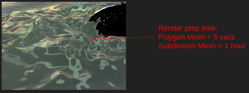
Subdivision Mesh
Input faces of a subdivision mesh define a set of “patches”. Usually, the input faces are referred to as the “control cage”.
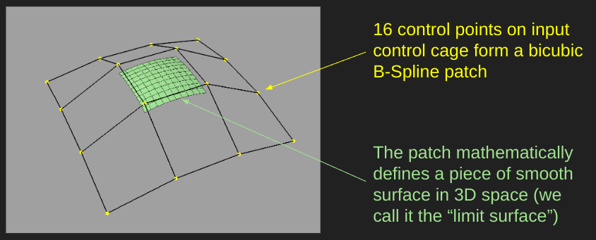
Subdivision meshes can provide a smooth/continuous rendering result through an input control cage with a small face count. This is most useful for character and organic surfaces.
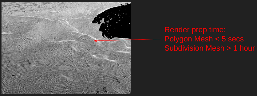
Polygon Mesh
Input faces of a polygon mesh are sent to the renderer with minimum processing, and all input vertices stay where they are told without any patch function remapping.
Polygon meshes have a much faster preprocess time. If the input face count is already really dense, it may already look good enough. It also suits low LOD assets.
Side-by-side Comparison
| Subdivision Mesh | Polygon Mesh |
|---|---|
| Smooth, continuous surface | Not tangent-continuous (faceted) surface (smooth normal option can ease this issue) |
| Longer render prep time | Short render prep time |
| Low disk usage (rendering stage memory can still be high if resolution is high) | |
| Topology sensitive (not every mesh is a good control cage) | No mesh topology restrictions |
Subdivision Mesh Pitfalls
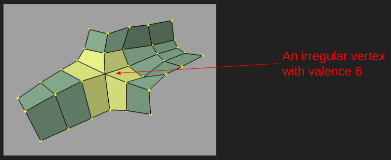
Irregular Vertices
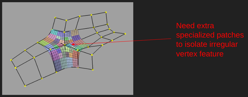
We use the Catmull-Clark subdivision algorithm, which is quad-friendly. Non-quad faces will be quadrangulated into quads. Irregular vertices are not Catmull-Clark friendly.
The underlying library is OpenSubdiv, which assumes irregular vertices and non-quad faces are rare cases.
Unsuitable Meshes
Not all meshes are modeled for subdivision mesh purposes. FX-exported simulations and Z-brush sculpted meshes often are not. In these cases, the render prep time can soar, and the CPU can be underutilized.
Optimize Your Scene
Turn on Logging
The -info runtime parameter can help you track down abnormal tessellation times. This will produce logs that will
break down the tessellation time per asset (search for the header “Tessellation Time” in the resulting log).
Tessellation vs Subdivision
Subdivision operates on a cage and produces a finer cage.
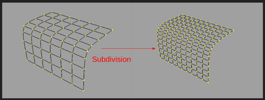
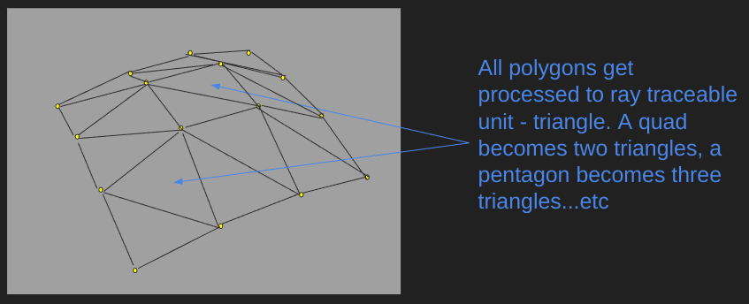
Tessellation operates on a surface and produces ray-traceable faces.
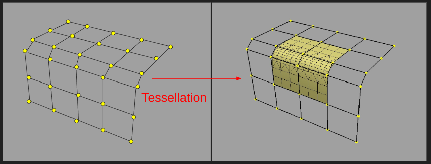
MoonRay provides control over the tessellation (mesh_resolution), and subdivision is handled automatically.
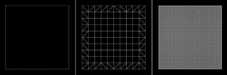 Left-to-right: mesh_resolution 1, 10, 100
Adaptive Tessellation
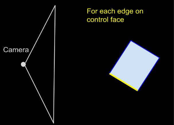
With adaptive tessellation, asset tessellation resolution is based on the camera view. It is enabled when adaptive_error, which represents the max allowable difference in pixels, is set to a value greater than 0. Each edge on a control face is tessellated based on a screen-space heuristic. The mesh_resolution attribute marks the maximum resolution in adaptive tessellation.
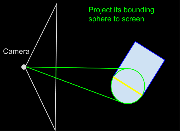
Edge resolution
The edge resolution is calculated as follows:
Edge resolution = min( projected pixel height / adaptive error, mesh resolution )
For example:
- projected pixel height: 20
- left column: adaptive error
- top row: mesh resolution
| 100 | 10 | 5 | |
|---|---|---|---|
| 1 | 20 | 10 | 5 |
| 2 | 10 | 10 | 5 |
| 4 | 5 | 5 | 5 |
Choosing an adaptive error value
A larger adaptive error means:
- More addressive resolution fall-off when mesh moves away from the camera
- More memory savings
- Higher chances of popping artifacts when moving the camera
An adaptive error of 2 is generally a good starting point, and you can decrease adaptive error to below 1 if you want to increase detail. You can crank up mesh_resolution to something impossible for uniform tessellation when adaptive_error > 0.