RdlMeshGeometry
Overview
RdlMeshGeometry generates either a polygonal or subdivision mesh defined soley by the node’s parameters.
The example below generates a single quad polygon.
RdlMeshGeometry("shape_basic") {
    ["vertex_list"] = { Vec3(0, 0, 0),
                        Vec3(0, 1, 0),
                        Vec3(1, 1, 0),
                        Vec3(1, 0, 0) },
    ["vertices_by_index"] = { 0, 1, 2, 3},
    ["face vertex count"] = { 4 },
}
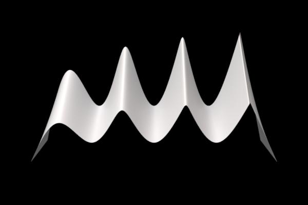
Advanced subdivision mesh features such as creasing are also supported. The example below generates a mesh with creases.
RdlMeshGeometry("shape_creases") {
    ["node xform"] = translate(-4, -2, 0),
    ["vertex list"] = { Vec3(0, 0, 0), Vec3(0, 0, -1), Vec3(0, 0, -2),
                        Vec3(1, 2, 0), Vec3(1, 3, -1), Vec3(1, 4, -2),
                        Vec3(2, 0, 0), Vec3(2, 0, -1), Vec3(2, 0, -2),
                        Vec3(3, 2, 0), Vec3(3, 3, -1), Vec3(3, 4, -2),
                        Vec3(4, 0, 0), Vec3(4, 0, -1), Vec3(4, 0, -2),
                        Vec3(5, 2, 0), Vec3(5, 3, -1), Vec3(5, 4, -2),
                        Vec3(6, 0, 0), Vec3(6, 0, -1), Vec3(6, 0, -2),
                        Vec3(7, 2, 0), Vec3(7, 3, -1), Vec3(7, 4, -2),
                        Vec3(8, 0, 0), Vec3(8, 0, -1), Vec3(8, 0, -2) },
    ["vertices by index"] = { 0,  3,  4,  1,   1,  4,  5,  2,
                              3,  6,  7,  4,   4,  7,  8,  5,
                              6,  9, 10,  7,   7, 10, 11,  8,
                              9, 12, 13, 10,  10, 13, 14, 11,
                             12, 15, 16, 13,  13, 16, 17, 14,
                             15, 18, 19, 16,  16, 19, 20, 17,
                             18, 21, 22, 19,  19, 22, 23, 20,
                             21, 24, 25, 22,  22, 25, 26, 23},
    ["face vertex count"] = {4,4, 4,4, 4,4, 4,4, 4,4, 4,4, 4,4, 4,4},
    ["subd crease indices"]     = { 3, 4,  4, 5,    9,10, 10,11,
                                   15,16, 16,17,   21,22, 22,23},
    ["subd crease sharpnesses"] = { 0.0,   0.0,     1.5,   1.5,
                                    3.0,   3.0,    10.0,  10.0},
    ["is subd"] = true,
    ["subd scheme"] = "catclark",
    ["subd resolution"] = 20
}
The above code generates this creased mesh:
Attribute Reference
Geometry attributes
reverse_normals
Bool
default: False
enable to reverse the normals in the geometry
side_type
Int enum
0 = “force two-sided” (default)
1 = “force single-sided”
2 = “use mesh sidedness”
set single sidedness of the mesh, will affect the visibility of the mesh based on normal direction
Labels attributes
label
String
default:
label used in material aov expresssions
shadow_receiver_label
String
default:
Label used to associate Geometry objects into ShadowReceiverSets. Using this in combination with the ["shadow_exclusion_mappings"] attribute, shadows from specified geometries or their parts can be suppressed from casting shadows onto one or more specified sets.
Mesh attributes
adaptive_error
Float
default: 0.0
The maximum allowable difference in pixels for subdivison mesh adaptive tessellation (each final tessellated edge won't be longer than n pixels if adaptive error is set to n). A value of 0 disables adaptive tessellation, reverting to uniform tessellation, which sometimes is more stable in animation. Adaptive tessellation is not supported for instances. The maximum tessellation won't exceed the value specified in mesh_resolution. This prevents excessive tessellation when the mesh is extremely close to the camera.
face_vertex_count
IntVector
default: {}
List of vertices per face, used in conjunction with vertices_by_index to construct the mesh
is_subd
Bool
default: True
If true, a SubdivisionMesh primitive will be created - PolygonMesh otherwise
mesh_resolution
Float
default: 2.0
The maximum resolution to which a mesh will be tessellated. NOTE: to prevent t-junctions, only even values are supported. If "mesh resolution" is set to n, it will first be rounded up to N=n+1 for odd n, N=n for even n. An edge on an input face will then be tessellated to at most N segments. If "adaptive error" is set to 0, every edge on the input face will be uniformly tessellated to N segments. Otherwise the mesh will tessellated adaptively based on its relationship to the camera.
normal_list
Vec3fVector
default: {}
If the mesh is using normals, store them per face-vertex in this list
orientation
Int enum
0 = “right-handed” (default)
1 = “left-handed”
When set to "left-handed", normals are generated using the left-handed rule. This reverses the direction of generated normals, and which side of surfaces is considered the front, without affecting supplied normals.
part_face_count_list
IntVector
default: {}
List of the number of faces belonging to the part with corresponding index in 'part list'.
part_face_indices
IntVector
default: {}
List of face indices. No index should have a value greater than the size of 'face_vertex_count'
part_list
StringVector
default: {}
List of part names, used in conjunction with 'part face count list' and 'part faces indicies' to assign per-part materials
smooth_normal
Bool
default: True
Generates smooth shading normals on a PolygonMesh when the mesh doesn't provide shading normals
subd_boundary
Int enum
0 = “none”
1 = “edge only”
2 = “edge and corner” (default)
Boundary interpolation: Corners, Edges or None
subd_corner_indices
IntVector
default: {}
List of indices for each corner vertex with an assigned sharpness.
subd_corner_sharpnesses
FloatVector
default: {}
Sharpness value for each corner vertex.
subd_crease_indices
IntVector
default: {}
List of vertex index pairs for each crease edge with an assigned sharpness.
subd_crease_sharpnesses
FloatVector
default: {}
Sharpness value for each crease edge.
subd_fvar_linear
Int enum
0 = “none”
1 = “corners only” (default)
2 = “corners plus1”
3 = “corners plus2”
4 = “boundaries”
5 = “all”
Face-varying linear interpolation: None, Corners Only, Corners Plus 1 or Plus 2 (RenderMan), Boundaries, or All
subd_scheme
Int enum
0 = “bilinear”
1 = “catclark” (default)
CatClark or Bilinear
uv_list
Vec2fVector
default: {}
If the mesh is using UVs, store them per face-vertex in this list
vertex_list_0
Vec3fVector
default: {}
List of vertex positions used by the mesh at motion step 0
vertex_list_1
Vec3fVector
default: {}
If the mesh is in motion, the vertex positions for the second motion step are stored in this attribute
vertices_by_index
IntVector
default: {}
List of vertex indices used to construct the mesh using the vertex list
Motion Blur attributes
accleration_list
Vec3fVector
default: {}
Optionally declared vertex accelerations for quadratic motion interpolation
curved_motion_blur_sample_count
Int
default: 10
Number of time samples generated along each curve when using curved motion blur
motion_blur_type
Int enum
-1 = “best” (default)
0 = “static”
1 = “velocity”
2 = “frame delta”
3 = “acceleration”
4 = “hermite”
Motion blur type for PolygonMesh/Points/Curves.
"static" will treat the mesh as static.
"velocity" will blur using the supplied vertex positions and velocities.
"frame delta" will interpolate between the two supplied vertex positions.
"acceleration" will blur using the supplied vertex positions, velocities and accelerations.
"hermite" will use supplied pair of positions and pair of velocities to interpolate along a cubic Hermite curve.
"best" will use choose the method which provides the highest quality given the available data.
primitive_attribute_frame
Int enum
0 = “first motion step”
1 = “second motion step”
2 = “both motion steps” (default)
Which frame(s) do we take the primitive attributes from?
O : first motion step
1 : second motion step
2 : both motion steps
use_rotation_motion_blur
Bool
default: False
If "xform" is time varying and motion blur is enabled, enabling this feature can produce a curved rotation trail. Enabling this feature will disable adaptive tessellation for this mesh
velocity_list_0
Vec3fVector
default: {}
Optionally declared explicit vertex velocities to use instead of vertex positions from a second motion step'
velocity_list_1
Vec3fVector
default: {}
Optionally declared second set of vertex velocities together with vertex positions from the second motion step for cubic motion interpolation
velocity_scale
Float
default: 1.0
Adjusts magnitude of velocity-based motion blur
Ray Tracing attributes
ray_epsilon
Float
default: 0.0
When a secondary ray is fired, anything within this distance of the intersection point will be ignored. Instead, it is considered part of the current intersection's geometry. If zero, an automatically calculated epsilon will be used.
shadow_ray_epsilon
Float
default: 0.0
When a shadow ray is fired, anything within this distance of the intersection point will be ignored. If this value is less than "ray_epsilon", then it has no additional effect.
User Data attributes
primitive_attributes
SceneObject Vector
default: {}
Vector of UserData. Each key/value pair will be added as a primitive attribute of the mesh.
Visibility attributes
visible_diffuse_reflection
Bool
default: True
whether the geometry is visible in diffuse reflection
visible_diffuse_transmission
Bool
default: True
whether the geometry is visible in diffuse transmission
visible_glossy_reflection
Bool
default: True
whether the geometry is visible in glossy reflection.
visible_glossy_transmission
Bool
default: True
whether the geometry is visible in glossy transmission (refraction).
visible_in_camera
Bool
default: True
whether the geometry is visible to camera rays
visible_mirror_reflection
Bool
default: True
whether the geometry is visible in miror reflection.
visible_mirror_transmission
Bool
default: True
whether the geometry is visible in miror transmission (refraction).
visible_shadow
Bool
default: True
whether the geometry casts shadows
visible_volume
Bool
default: True
whether the geometry is visible in indirect volume rays
General attributes
contains_camera
Bool
default: False
Specifies whether the geometry contains the camera and should be used for IOR tracking. This should not be changed by the user -- they should instead attach the relevant geometry to the camera, which will then flag this geometry.
dicing_camera
SceneObject
default: None
Alternate camera that is used for adaptive tessellation. This is useful if you want adaptive tessellation to behave consistently in a sequence, regardless of what the main camera is doing
node_xform
Mat4d blurrable
default: [ [ 1, 0, 0, 0 ], [ 0, 1, 0, 0 ], [ 0, 0, 1, 0 ], [ 0, 0, 0, 1 ] ]
The 4x4 matrix describing the transformation from local space to world space.
references
Geometry Vector
default: {}
list of geometries that geometry procedural can reference during procedural generate/update stages. For example, an instancer geometry procedural can instance primitives generated by the reference geometry procedural.
shadow_exclusion_mappings
String
default:
A space-separated list of mappings of the form A:B where:
A is a comma-separated list of names of parts of this Geometry, or an asterisk to specify the whole geometry;
B is a comma-separated list of shadow receiver set labels established using the ["shadow_receiver_label"] attribute, or an asterisk to specify to all such sets in the scene.
For each of the listed mappings, shadows from the parts specified in A will be suppressed from casting onto any geometries in the ShadowReceiverSets specified in B.
**Note: no part name should appear more than once in the string, otherwise the behavior is undefined.**
static
Bool
default: True
disable if the geometry will be updated between frames
use_explicit_shading_attributes
Bool
default: False
Enable the use of explicit shading attributes (N, dPds, dPdt) if they are present
use_local_camera_motion_blur
Bool
default: False
Enables experimental feature that also attempts to remove the camera blur in the local regions
use_local_motion_blur
Bool
default: False
Enables the local motion blur feature, which makes the geometry procedural responsible for handling all of the geometry's motion and allows for custom effects